IRIG 106 Chapter 4 Telemetry / Pulse Code Modulation (PCM)
Pulse Code Modulation (PCM) is a method used to digitally encode and transmit, traditionally analogue, signals from one part of a telemetry system to another. Whilst it is steadily being replaced by Ethernet based networked instrumentation, PCM still plays a significant part and a knowledge of how it works provides a great introduction to Flight Test Instrumentation. The Inter Range Instrumentation Group produce the standards governing the format of PCM for use in digital flight data recording. These standard are defined in IRIG 106 Chapter 4 and generally revisited every two years.
A short history
Pulse Code Modulation was invented as far back as 1937 by the British engineer Alec Reeves while working in France for American manufacturing company International Telephone and Telegraph (ITT). Though Alec described theory and advantages of PCM, no practical applications resulted at the time, likely due to a limitation of the day’s technology.
Today, in addition to its use in Flight Test Instrumentation, PCM is the standard form for digital audio in computers and telephone systems. It was also the technology underlying Blu-ray, Compact Disc and DVD formats.
First steps in creating a PCM stream
Let us assume we have a single turboprop aircraft, and the measurements we wish to telemeter are air temperature, air speed, engine temperature, engine temperature, fuel level, and acceleration. Sensors for these measurements will be connected to a flight test data recorder that will condition and convert the signals into PCM format for recording to compact flash (or other storage) and output to a telemetry transmitter which in turn will convert to an FM signal for an antenna as per the schematic below.

Fig.1 - Basic Onboard FTI System
Focusing on the air temperature measurement, the thermocouple voltage is conditioned and passed through a Low Pass Filter (LPF) to remove any unnecessary high frequency components. A Digital to Analogue Convertor (DAC) is then employed to convert the voltage into a train of pulses of ones and zeros. This is our first sample and is in the form of a binary word. The analogue to digital conversion continues at uniform intervals.
The word length is also referred to as the sample’s bit depth, the frequency of the uniform intervals is referred to as the sample rate.
Thus there are two basic properties that determine the sample’s fidelity to the original analogue signal. A higher word length / bit depth increases a sample’s amplitude resolution, whilst a higher sample rate increases a sample’s resolution in the time axis.
Nyquist Theorem recommends that the sample rate should be at least twice that of the maximum signal frequency. In practice it is not uncommon to sample 5 or 10 times the maximum signal frequency.
Slow changing measurements such as fuel level need only be sampled slowly, whilst accelerometers may require a faster sample rate. We’ll come back to this later, for the moment it’s enough that this conversion from analogue to digital takes place for each of our six measurements using the same sample rate.
Commutation and Time Division Multiplexing
We will be wanting to send our six measurements in one PCM stream from data recorder to other devices such as an RF Transmitter.
The process of combining each word into one PCM data stream is called commutation. The job of commutation given to the Time Division Multiplexer (TDM). The TDM does this by taking the word from each consecutive sensor / channel, and compiling them into a Frame.
It’s important to note that each word only contains the measured value, no identifying tag, scaling, nor units. The words are attributeless, and indeed a method will be required to make sense of the words. This is the job of the TMATS file, and as you may have guesses, we’ll come to that later.
An initial look at the Time Division Multiplexer and we might picture the process of commutating our PCM stream to look something like this…

Fig 2. - Visualization of Time Division Multiplexing
Now we need a method for the receiving device to identify the start of a frame so that it can correctly extract the words from the PCM stream. Fortunately we have that method, it’s called the Frame Sync pattern.
The Frame Sync pattern, Sub Frame Identifier & Major Frame
The Frame Sync pattern (FS) is a sequence of binary with a very low probability of occurring as a sample’s word. The longer the Frame Sync word the lower the probability of occurrence as data. Here a short table of examples.
| FS Pattern Width |
Binary Pattern | ||||||||
| 16 | 1110 | 1011 | 1001 | 0000 | |||||
| 17 | 1 | 1110 | 0110 | 1010 | 0000 | ||||
| 18 | 11 | 1100 | 1100 | 0100 | 0000 | ||||
| 19 | 111 | 1100 | 1100 | 1010 | 0000 | ||||
| 20 | 1110 | 1101 | 1110 | 0010 | 0000 | ||||
| 21 | 1 | 1101 | 1101 | 0010 | 1100 | 0000 | |||
| 22 | 11 | 1100 | 1101 | 1010 | 1000 | 0000 | |||
| 23 | 111 | 1010 | 1110 | 0110 | 1000 | 0000 | |||
| 24 | 1111 | 1010 | 1111 | 0011 | 0010 | 0000 | |||
| 25 | 1 | 1111 | 0010 | 1101 | 1100 | 0100 | 0000 | ||
| .... | |||||||||
| 32 | 1111 | 1110 | 0110 | 1011 | 0010 | 1000 | 0100 | 0000 | |
| 33 | 1 | 1111 | 0111 | 0100 | 1110 | 1001 | 0100 | 1001 | 1000 |
Fig. 3 – Table of Frame Sync Patterns
In addition to the Frame Sync pattern, a Sub Frame Identifier (SFID) is placed after the Frame Sync pattern. The Sub Frame Identifier is needed because of the different sample rates sometimes used for each channel. Thus the construction of a frame (or Sub Frame) may be different from the proceeding frame.
If we wanted to visualise a PCM stream commutated to for a shared sample rate, we could create a table that look like this, where the multiple rows of the table are called the Major Frame.
| Normal Commutation | |||||||||
| FS | SFID | Ch. 1 Word 1 | Ch. 2 Word 1 | Ch. 3 Word 1 | Ch. 4 Word 1 | Ch. 5 Word 1 | Ch. 6 Word 1 | Major Frame | |
| FS | SFID | Ch. 1 Word 2 | Ch. 2 Word 2 | Ch. 3 Word 2 | Ch. 4 Word 2 | Ch. 5 Word 2 | Ch. 6 Word 2 | ||
| FS | SFID | Ch. 1 Word 3 | Ch. 2 Word 3 | Ch. 3 Word 3 | Ch. 4 Word 3 | Ch. 5 Word 3 | Ch. 6 Word 3 | ||
Fig. 4 – Visualization of a Normally Commutated PCM Major Frame
But if we sample the Air temperature (Ch. 1), Engine Temperature (Ch.3 ), and Fuel Level (Ch. 5) at third the sample rate of the other channels then Sub Commutation is required and our Major Frame may be visualised more like this.
| Sub Commutation | |||||||
| FS | SFID | Ch. 1 Word 1 | Ch. 2 Word 1 | Ch. 6 Word 1 | Ch. 6 Word 1 | Major Frame | |
| FS | SFID | Ch. 3 Word 1 | Ch. 2 Word 2 | Ch. 4 Word 2 | Ch. 6 Word 2 | ||
| FS | SFID | Ch. 5 Word 1 | Ch. 2 Word 3 | Ch. 4 Word 3 | Ch. 6 Word 3 | ||
 Sub Com. Ch. Sub Com. Ch. |
|||||||
Fig. 5 – Visualization of a Sub Commutated PCM Major Frame
If on the other hand the acceleration is sampled at twice the sample rate of the other channels then we require Super Commutation, and our Major Frame could be visualised more like this.
| Super Commutation | ||||||||||
| FS | SFID | Ch. 1 Word 1 | Ch. 2 Word 1 | Ch. 6 Word 1 | Ch. 3 Word 1 | Ch. 4 Word 1 | Ch. 5 Word 1 | Ch. 6 Word 2 | Major Frame | |
| FS | SFID | Ch. 1 Word 2 | Ch. 2 Word 2 | Ch. 6 Word 3 | Ch. 3 Word 2 | Ch. 4 Word 2 | Ch. 5 Word 2 | Ch. 6 Word 4 | ||
| FS | SFID | Ch. 1 Word 1 | Ch. 2 Word 3 | Ch. 6 Word 5 | Ch. 3 Word 3 | Ch. 4 Word 3 | Ch. 5 Word 3 | Ch. 6 Word 6 | ||
 Super Com. Ch. |
 Super Com. Ch. |
|||||||||
Fig. 6 – Visualization of a Super Commutated PCM Major Frame.
Whilst it’s likely that the hardware producing Major Frames is doing so in a continuous process, outputting a continuous stream of binary rather than delaying until a Major Frame has been constructed, a complete explanation requires a further visualisation. We need to convert the grid pattern of the Major Frame into a continuous PCM stream.
Taking the example of super commutated Major Frame above this may be visualised like this, where the direction of flow is from left to right.
| Structure of a PCM Stream | ||||||||||||||||||||
| ...... | SF ID |
FS | Ch. 6 W. 4 | Ch. 5 W. 2 | Ch. 4 W. 2 | Ch. 3 W. 2 | Ch. 6 W. 3 | Ch. 2 W. 2 | Ch. 1 W. 2 | SF ID |
FS | Ch. 6 W. 2 | Ch. 5 W. 1 | Ch. 4 W. 1 | Ch. 3 W. 1 | Ch. 6 W. 1 | Ch. 2 W. 1 | Ch. 1 W. 1 | SF ID |
FS |
| → Direction of PCM Stream → | ||||||||||||||||||||
Fig. 7 – Visualization of the structure of a PCM Stream
The IRIG-106 Chapter 4 Telemetry Standard imposes strict rules on the structure of a compliant PCM stream. This standard should be consulted for full specifications and are beyond the general explanation given here.
You might be forgiven for thinking that this PCM stream is transmitted as a series of the ones and zeros that make up its component parts. It can be, but there are alternative formats determined by the Binary Bit Representation.
Binary Bit Representation
There are different ways a PCM stream may represent the ones and zeros of the binary levels. The IRIG 106 Chapter 4 Telemetry Standard lists and describes six Binary Bit Representations, only one of which should be used in a single PCM stream. To do otherwise would be confusing. These representations are shown below.
| Code | Logical Waveform Levels |
Coded Waveforms | Code Definitions | |||||||||||||||||
| NRZ-L | 1 0 |
 |
Non Return to Zero - Level NRZ-L 1 “ONE” is represented by one level 0 “ZERO” is represented by the other level |
|||||||||||||||||
| NRZ-M | 1 0 |
 |
Non Return to Zero - Mark NRZ-M 1 “ONE” is represented by a change in level 0 “ZERO” is represented by NO change in level |
|||||||||||||||||
| NRZ-S | 1 0 |
 |
Non Return to Zero - Space NRZ-S 1 “ONE” is represented by NO change in level 0 “ZERO” is represented by a change in level |
|||||||||||||||||
| Biϕ-L | 1 0 |
 |
Bi-Phase - Level(1) Biϕ-L 1 “ONE” is represented by a “ONE” level with transition to the “ZERO” level 0 “ZERO” is represented by a “ZERO” level with transition to the “ONE” level |
|||||||||||||||||
| Biϕ-M | 1 0 |
 |
Bi-Phase - Mark(1) Biϕ-M 1 “ONE” is represented by NO level change at the beginning of the bit period 0 “ZERO” is represented by a level change at the beginning of the bit period |
|||||||||||||||||
| Biϕ-S | 1 0 |
 |
Bi-Phase - Space(1) Biϕ-S 1 “ONE” is represented by a level change at the beginning of the bit period 0 “ZERO” is represented by a NO level change at the beginning of the bit period |
|||||||||||||||||
| Note: The Biϕ codes may be derived from the corresponding NRZ codes by inverting the level for the last half of each bit interval. | ||||||||||||||||||||
Fig. 8 – Binary Bit Representation
Product data sheets will reference which Binary Bit Representations they support. There are others too, including delta modulation (DM). DM is the simplest form of Differential Pulse Code Modulation (DPCM) in which the difference between successive samples are encoded into a data stream, but this is outside the scope of this article.

Bit Rate
The speed of the PCM stream, i.e. the number of bits transmitted per second is known as the Bit Rate. When choosing components for an FTI System it is important to consider the maximum bit rate of each component. For example Safran Data Systems MDR data recorder can handle a bit rate of up to 800 Mbps, whilst on the ground side, their RX-1 RF receiver can handle a Bit Rate = from 10 kbps to 40 Mbps. From this it clear that you can record more information than you can transmit, at least across one frequency and with one transmitter.
IRIG 106 Chapter 4 states that the minimum Bit Rate shall be 10 bps, and greater than 10 Mbps rates for class II applications. It also remain within 0.1 percent of the specified rate.
Into the Frequency Modulation (FM) domain
Whilst within a networked Data Acquisition System, the PCM stream can be sent direct to a recorder or disseminating device, and perhaps be decommutated for display on-board. If the PCM stream is required on the ground, a telemetry transmitter will be required to convert the binary into FM or other radio frequency modulation such as SOQPSK (Shaped Offset Quadrature Phase Shift Keying) which might be the subject of another guide, but certainly not this one.
The process of frequency modulation employed in telemetry is known as Binary Frequency-Shift Keying (BFSK). The Binary PCM stream is first passed through a low pass filter and then used to modulate the frequency of a carrier wave. If we were to look at the NRZ-L binary bit representation again, it’s FM equivalent would look similar to that shown below, where the carrier frequency is that of the telemetry band chosen for the transmission.
| Code / Signal | Coded Waveforms | Input / Output |
| NRZ-L |  |
◄ Input |
| NRZ-L After Low Pass Filter |
 |
|
| Carrier Wave |  |
◄ Input |
| FM Modulated Signal |
 |
► Output |
| Note. Frequencies selected for depiction only. | ||
Fig. 9 – Visualization of a PCM Stream converted to a Frequency Modulated signal
Carrier Frequencies
Flight Test Telemetry traditionally operates with three carrier band frequencies which the IRIG 106 standards subdivide into upper, middle and lower bands.
| Band | Frequency Range | Comments |
| Lower L | 1.435 to 1.535 GHz | L band is also shared in some regions by mobile phones (1452 – 1492 GHz), GPS (176.45 MHz (L5), 1227.60 MHz (L2), 1381.05 MHz (L3), and 1575.42 MHz (L1)). |
| Lower S | 2.200 to 2.300 GHz | S band is also used in some regions by airport radar, some communication satellites, cordless phones, Bluetooth devices, WiFi (2.4GHz), and numerous other wireless devices. |
| Upper S | 2.310 to 2.395 GHz | |
| Lower C | 4.400 to 4.940 GHz | C band is also used for satellite communications, some WiFi devices, cordless telephones, and some surveillance and weather radar systems. |
| Middle C | 5.091 to 5.150 GHz | |
| Upper C | 5.925 to 6.700 GHz |
Fig. 10 – Table of Telemetry Carrier Frequencies
The Ground System
A modern flight test ground station can be a very sophisticated affair. There may be multiple tracking antenna receiving multiple telemetry bands. This in turn requires multiple receivers, and a device for selecting the best signal source. The RF signals from each of the antennas may be recorded before any conversion back into a digital signal is begun, thus enabling backup and redundancy in case something goes wrong. There will be antenna control units, and mission control software, range cameras, etc.. But for the ease of our story, let us picture a simple ground telemetry system as illustrated below and consisting of an antenna, receiver, recorder and replay unit, and PC running decommutation and display software.

Fig. 11 – A simple ground telemetry system.
The antenna tracks and receives the RF signal from the telemetry transmitter and antenna on-board the aircraft. The RF signal is converted into an analogue electrical signal that is transmitted through cables or fibre optics to the telemetry control room where it enters the RF receiver. The receiver recovers the raw data stream from the RF carrier, which at this stage is a noisy and unsynchronized raw data stream.
Bit Synchronisation
For the noisy stream of raw data to be of any use, the RF Receiver must it clean up. The Bit Synchroniser (Bit Sync) circuitry does just this. Locking onto the peaks and troughs, the Bit Sync reconstructs the data signal as a clean PCM stream. In parallel the Bit Sync generates a synchronised clock pulse that matches the data rate of the original PCM stream. The output of the Bit Sync is thus both a cleaned PCM pulse, and a clock pulse.
| Signal State | Waveforms | Input / Output |
| FM Modulated Signal |
 |
◄ Input |
| Noisy PCM stream extracted from FM modulated carrier |
 |
|
| Reconstructed NRZ-L Data |
 |
► Output |
| Synchronized Clock |
 |
► Output |
| Note. Frequencies selected for depiction only. | ||
Fig. 12 – The Bit Sync reconstructs the PCM data stream and clock from the RF modulated signal
The accuracy of the reconstruction is known as both the Bit Error Rate and Bit Error Ratio.

The Bit Error Rate and Bit Error Ratio (BER)
The Bit Error Rate is the number of bit errors per unit of time.
The Bit Error Ratio is the number of bit errors divided by the total number of transferred bits, and is often expressed as a percentage.
Let us look at the same bit sequence used in the Binary Bit Representation example.
101100011010 is transmitted once a second
101100110010 is instead received
Then that is two bit errors is 2/second.
2 flipped bits in 12 gives a Bit Error Ratio of 0.1666.
There are a number of factors affecting the BER. The strength of the transmitted signal may be insufficient for the distance and capabilities of the receiving antenna. There may be noise, interference, multipath problems, or bit sync problems. Different solutions have been developed to reduce the effect of such factors.
Frame Synchronisation (Sync)
Having been cleaned by the Bit Synchroniser, the PCM stream needs to be made ready for decommutation. This is done within the Frame Synchroniser which maybe hardware or software based.
The Frame Synchroniser first compares the incoming bit stream with known Frame Sync patterns (this stage is often called searching). Once a potential Frame Sync pattern has been tentatively identified, the Frame Synchroniser will count bits until it verifies that the same Frame Sync pattern re-occurs, at which point it will make another comparison, and another (this stage is often called verification). All being well, the Frame Sync will Lock, and Minor and Major Frames can be rebuilt ready for decommutation.
There is an expectation within the design that the incoming PCM stream may contain errors. These may be flipped bits of slipped bits. For this reason once Locked, the Frame Synchroniser will continue checking for the Frame Sync pattern.
Different manufacturers may use certain tolerances within the Frame Synchroniser to compensate for errors in the PCM stream. These may include …
Search to Lock – The number of occasions the Frame Sync pattern is found back-to-back before frame lock is achieved.
Sync Pattern Bit Errors – The acceptable number of mis-matched bits in the Frame Sync pattern.
Bit Aperture – The acceptable number of bits by which the Frame Sync pattern may be early or late.
Lock to Search – The number of successive invalid Frame Sync patterns detected before the Frame Synchroniser begins to search for again for the Frame Sync pattern.
Decommutation
From the Frame Synchroniser we have our Major and Minor frames. To decode its contents we need a TMATS (Telemetry Attributes Transfer Standard) file. IRIG 106 Chapter 9 provides practical guidance and best practices in generating and using TMATS files.
Essentially a TMATS file provides the decommutator with the information to identify each word in the frame, in our example air temperature, air speed, engine temperature, engine temperature, fuel level, and acceleration. A further level within the TMATS file provides information on how the binary value should be scaled and which engineering units should be applied. Depending on the systems sophistication the TMATS file may even contain information about the make, model, and serial number of the transducer.
It is useful in reducing errors to use a TMATS file for decommutation that was created by the same software used to configure the data acquisition. Safran Data Systems eZ Setup and eZ Processing software supports the sharing of the same TMATS files. TMATS Files are typically in XML (eXtensible Markup Language) format.
PCM Data Acquisition:
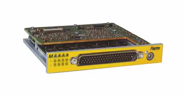
Heim / Safran Data Systems flight test recorders and data acquisition units can accept multiple PCM data channels on separate physical inputs.
Input Modules for the MDR Data Recorder include ...

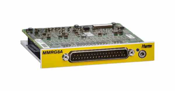
MMRG8, MMRG8A
The MMRG8 and MMRG8 are 8 channel PCM merger input modules.

MTVME-TM7B-BAA
The MTVME-TM7B-BAA is a hybrid interface module that contains 6 channels of PCM inputs, 4 voice inputs, 3 telemetry transmit outputs, and 2 Ethernet input / outputs.

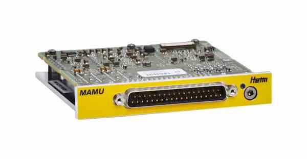
MAMU
The MAMU module supports 2 PCM input channels, 2 dual –redundant MIL-STD-1553B input channels and 8 ARINC 429 input channels
Input Module for the XMA Data Acquisition Unit

XMA RSX - 4 x RS-232/422/485 & PCM Channels
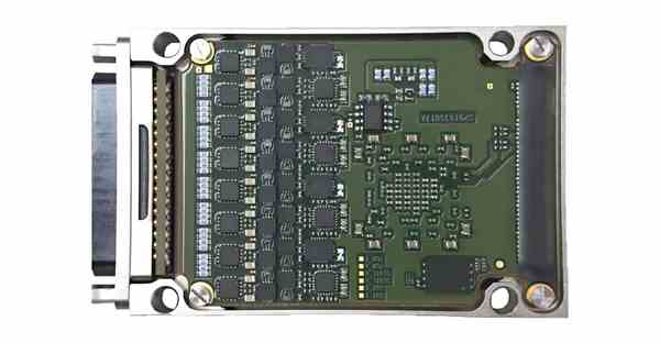
The RSX module is an application module from Safran Data Systems XMA Series. Like other application modules, the RSX module is meant to be inserted in a XMA Data Acquisition Unit (DAU).
-
Up to 4 RS422/485 asynchronous channels
-
Up to 2 RS422/485 synchronous channels (Data + Clock)
-
Up to 4 RS232 asynchronous channels
-
Up to 2 RS422 PCM synchronous channels (Data+Clock), up to 20Mbps
-
NRZ (L,M,S), RNRZ-L (scrambled NRZ-L), Bi-L,M,S
-
Customization of RS processing available on demand
Disclaimer: The information in this guide is designed to help you understand our products. It is correct to the best of our knowledge and at the time of writing. However Photo-Sonics International Limited does not accept any liability for its use. Instead the latest documentation from the relevant authority should be consulted.