ARINC 429 Avionic Data Bus
Introduction:
Since its inception in 1978, ARINC 429 has become the standard for avionic data buses on commercial aircraft. Military aircraft tend to use a similar bus governed by MIL-STD-1553. Unlike military or government standards, ARINC 429 was created by a private company, Aeronautical Radio, Inc. (ARINC), from which it takes it’s nomenclature. Also known as Mark 33 Digital Information Transfer System (DITS), ARINC 429, is one of many ARINC standards that continue to be developed by the Airlines Electronic Engineering Committee (AEEC) The last revision was published in January 2019, and is a chargeable purchase.
The standard defines the physical and electrical interface along with a digital data protocol to allow the sharing of air speed, heading, barometric altitude, wind direction, GPS, and other flight data from a single transmitting device, for example an Air Data Inertial Reference Unit (ADIRU), to a maximum of twenty receiving devices. By conforming to the ARINC 429 standard, devices from different manufactures will be compatible. ARINC 429 modules are available for Heim / Safran Data Systems flight data recorders and data acquisition units so that they two can tap into one or more avionics bus.

Fig.1 - Example of ARINC 429 Bus Topology including flight test data recorder.
Cabling and bit representation:
A unidirectional ARINC 429 data bus requires a shielded 75 ohm twisted pair cable, grounded at both ends. Receiving devices should be connected in parallel with the transmitter. A second twisted pair can be used if bi-directional communication is required.
Over this twisted pair, a tri-state modulation method is employed to help provide an interference free and fail safe transmission. In this bipolar, Return-to-Zero (RZ), format, a binary 1 is indicated by the signal going from NULL state (0 v) to a HIGH state (nominally +5 v) for the first half of the bit, before returning to the NULL state for the remaining half of the bit cycle.
A binary 0 is indicated by dropping from NULL state (0 v) to LOW state (nominally –5 v) for the first half of the bit before returning to the NULL state for the remaining half of the bit cycle.
N.B. The standard defines a 10 volt differential between HIGH and LOW state, also known as Data A and Data B levels which is how you will often see ARINC terminals labels on receiving devices. There is a tolerance to allow for the dropping voltage levels as the number of receiving devices increases from one to twenty. The standard will also define a tolerance for the rise and fall times of the signal.
Bits are transmitted at either low speed (12.5 kbit/s), or high speed (100 kbit/s). For those of you who crave the clarity of Boolean logic, that’s an exclusive OR, i.e. only one speed should be used on a single data bus.
| Return-to-Zero (RZ) representation of binary | |||||||||
| Binary | 1 | 0 | 1 | 0 | 1 | 1 | 0 | 0 | |
| Return-to-Zero representation |
HIGH NULL LOW |
 |
|||||||
A collection of 32 RZ coded bits become a word, and these carry the data across the bus in what ARINC refer to as Messages. Most Messages are 32 bit in length. When the transmitting device has no messages left to transmit, the bus returns to a NULL (0 v) state.
ARINC 429 Word Format:
Each ARINC word is a 32-bit value that contains five fields; the Label, SDI, the Data, SSM, and a final parity bit.
The diagram below shows the first transmitted bit on the right, the last on the left.
| ARINC 429 Word Format | |||||||||||||||||||||||||||||||
| P | SSM | LSB | Data | MSB | SDI | LSB | Label | MSB | |||||||||||||||||||||||
| 32 | 31 | 30 | 29 | 28 | 27 | 26 | 25 | 24 | 23 | 22 | 21 | 20 | 19 | 18 | 17 | 16 | 15 | 14 | 13 | 12 | 11 | 10 | 9 | 8 | 7 | 6 | 5 | 4 | 3 | 2 | 1 |
We can rotate this table through 90° and expand it to include a full description. For clarity were reversing the order of the bits.
| ARINC 429 Word Format, Expanded | |||||||||||||||||||||||||||||||||||||||||||||||||||||||||||||
| Section | Bit | Description | |||||||||||||||||||||||||||||||||||||||||||||||||||||||||||
| Label | 1 | Identifies the data with an octal number in the range 000 to 377, allowing up to 255 Information Identifiers used in a look up table. We’ll talk more about this later on.
|
|||||||||||||||||||||||||||||||||||||||||||||||||||||||||||
| 2 | |||||||||||||||||||||||||||||||||||||||||||||||||||||||||||||
| 3 | |||||||||||||||||||||||||||||||||||||||||||||||||||||||||||||
| 4 | |||||||||||||||||||||||||||||||||||||||||||||||||||||||||||||
| 5 | |||||||||||||||||||||||||||||||||||||||||||||||||||||||||||||
| 6 | |||||||||||||||||||||||||||||||||||||||||||||||||||||||||||||
| 7 | |||||||||||||||||||||||||||||||||||||||||||||||||||||||||||||
| 8 | |||||||||||||||||||||||||||||||||||||||||||||||||||||||||||||
| Source Destination Identifier |
9 | Optional, the SDI is used to signify the data source to the receiving device. If SDI is not used, these two bits can instead be used to increase the resolution of the data.
|
|||||||||||||||||||||||||||||||||||||||||||||||||||||||||||
| 10 | |||||||||||||||||||||||||||||||||||||||||||||||||||||||||||||
| Data | 11 | Commonly formatted as Discrete Data, Binary Coded Decimal (BCD), two's complement binary encoding (BNR), or a mixture. When BNR encoding is used bit 29 takes on special significance.
|
|||||||||||||||||||||||||||||||||||||||||||||||||||||||||||
| 12 | |||||||||||||||||||||||||||||||||||||||||||||||||||||||||||||
| 13 | |||||||||||||||||||||||||||||||||||||||||||||||||||||||||||||
| 14 | |||||||||||||||||||||||||||||||||||||||||||||||||||||||||||||
| ... | |||||||||||||||||||||||||||||||||||||||||||||||||||||||||||||
| 26 | |||||||||||||||||||||||||||||||||||||||||||||||||||||||||||||
| 27 | |||||||||||||||||||||||||||||||||||||||||||||||||||||||||||||
| 28 | |||||||||||||||||||||||||||||||||||||||||||||||||||||||||||||
| 29 | |||||||||||||||||||||||||||||||||||||||||||||||||||||||||||||
| Sign / Status Matrix |
30 | Indicates a negative or positive value, direction, validity, and testing depending on data type and formatting used. The following matrix provide definitions.
|
|||||||||||||||||||||||||||||||||||||||||||||||||||||||||||
| 31 | |||||||||||||||||||||||||||||||||||||||||||||||||||||||||||||
| Partity | 32 | Used for detecting errors in transmission. A receiver will expect an odd number of 1 bits in the word, and the parity bits is set to make this so. |
|||||||||||||||||||||||||||||||||||||||||||||||||||||||||||
More about Labels:
ARINC 429 data labels are octal numbers in the range 000 to 377, allowing for up to 255 Information Identifiers (for those new to Octal, there are no eights nor nines). These Information Identifiers act as a key in the index of a look up table. In fact there are multiple look up tables, typically one for each type of ARINC 429 transmitting equipment; Air Data Inertial Reference Unit, Flight Management Computer, radar, radio, GPS unit, etc.
A look up table should be provided when purchasing equipment that transmits IRIG 429, and will typically include information of data format (Discrete, BCD, or BNR), range, units, etc. Tables can also be found in the ARINC 429 standard documentation, but here is a flavour.
| Example ARINC Label Table Data | |||||
| Label (Octal) | Description | Format | Units | Range | Bits |
| 102 | Select Altitude | BNR | feet | 0 to 65535 | 12 |
| 210 | True Airspeed | BNR | kt | 0 to 511 / 1023 | 10 |
| 212 | Barometric Altitude Rate | BNR | fpm | 0 to 255 / 8191 | 9 |
Groups of similar equipment tend to use common look up tables with minor manufacture’s variations in data format. This allows some degree of interchangeability of parts.
ARINC 429 in Data Acquisition
Heim / Safran Data Systems flight test recorders and data acquisition units can accept multiple ARINC 429 data channels on separate physical inputs. Depending upon configuration and bit rate, they are able to record all the messages on the bus, or strip out only those messages defined as of interest.
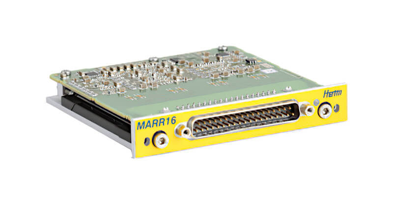
MDR Data Recorder - MARR16, MARR16A
The MARR16, MARR16A modules are dedicated input modules for recording messages on ARINC 429 data buses. Each module can be integrated in a MDR mainframe and combined with any other HEIM DATaRec® 4 MDR modules to a multi-channel recording system.

XMA Data Acquisition Unit - XMA-ARC
The XMA-ARC module is a dedicated input module for acquiring messages on ARINC 429 data buses. The 16 input channels are fully independent (Speed, Parity, filtering...). Additional status counters allow to analyse the traffic on the bus.
Disclaimer: The information in this guide is designed to help you understand our products. It is correct to the best of our knowledge and at the time of writing. However Photo-Sonics International Limited does not accept any liability for its use. Instead the latest documentation from the relevant authority should be consulted.