Precision Time Protocol (PTP)
Introduction:
Electronic devices connected to a computer network generally require a method to synchronise their individual clocks. On an Ethernet network, there are three options, and in order of increasing accuracy, they are Simple Network Time Protocol (SNTP), Network Time Protocol (NTP), and Precision Time Protocol (PTP).
As its name suggests, SNTP is a simplified version of NTP, differing from the latter in its error checking and time correcting algorithm. In use since before 1985, NTP is one of the oldest internet protocols and is accurate to tens of milliseconds on the internet and a few milliseconds on a Local Area Network.
Measurement and Control, financial transactions, mobile phone communications, and other technologies require increased accuracy and with clock synchronisation in the nanosecond range on a LAN, Precision Time Protocol is today’s method of choice.
Precision Time Protocol derives time from International Atomics Time (TAI), the number of seconds since the start of January 1st 1970. PTP devices are able to convert to Coordinated Universal Time (UTC) and account for leap seconds.
At the time of writing, 1650467317 seconds have passed since January 1st 1970 began, thus making it Wednesday 20th April 2022, 15:08:37 International Atomics Time (TAI), or 15:08:00 Coordinated Universal Time (UTC) subtracting the 37 leap seconds added since the count began.
PTP is fully defined by IEEE standard 1588 first published in 2002. A second non-backward compatible version 2 was published in 2008, and yet another in 2019 detailing enhancements that are backward compatible with IEEE 1588-2008.
Before going on to look at the PTP network topology, it’s worth a brief explanation of clock strata.

Clock Strata:
PTP and NTP use a hierarchical system of time sources in which there are multiple levels or stratum. A reference clock sits at the top most level is assigned the stratum number zero and is typically a GPS or a device with an atomic clock oscillator.
Any clock synchronised with a stratum 0 clock becomes a stratum 1 clock. Any clock synchronised with a stratum 1 clock becomes a stratum 2 clock, and so it continues to stratum 15, the stratum number indicating the distance from the reference clock rather than providing an indication of accuracy or reliability.
PTP Network Topology:
A PTP network requires PTP aware devices (routers, hubs, switches, etc.). Such devices can be classified as one of the following.
-
Grand Master Clock (GMC)
-
Master Clock (MC)
-
Boundary Clock (BC)
-
Transparent Clock (TC)
-
Slave Device
The Grand Master Clock is the primary time source for all other devices on the network. It itself acquires time from a GPS or an atomic clock oscillator. The GMC is expected to be a stratum 1 clock device. Both our MDR flight test data recorders and On-Time range of rugged and airborne network switches include the ability to act as a PTP Grand Master Clock when connected to a GPS aerial. Should a Grand Master or Master Clock be required, the ITS 6115G-3E Janus Time Code Generator is ideal.
A wide network may require a Master Clock. These are slaved to either a Grand Master Clock or other PTP clock. They are therefore a stratum 2 device or lower in the hierarchy. Frequently multiple Master Clocks exist upon a network, and in these circumstances a Best Master Clock Algorithm (BMCA) is used to calculate which is the accurate and can provide some redundancy in event of a failure. A Boundary Clock has multiple network connections and can accurately synchronize one network segment to another. One port is a slave to a GMC or MC, whilst the other ports act as a MC to its dependent Local Area Network.
A Transparent Clock was introduced in the PTP V2. These may modify the PTP message as it passes through it, correcting the timestamp as it does so. Transparent Clocks are usually network nodes such as switches.
A Slave Device sits at the bottom of the topology. It may be a PC, an IP Camera, or other device that received and uses the PTP timecode for part of it functionality. Our Kappa FE-320 IP cameras are examples of a slave device that uses PTP V2 to accurately timestamp IP video streams.
|
|
How PTP Works:
Now let us take a look at how PTP actually works. Let us do so by using a simple example examining the timestamps during the synchronisation of a Slave Device to a Master Clock Device.
We will use some easy numbers, and leap into the future, 18th May 2033, at 03:33:20 (TAI), when 2000000000 seconds have passed since initiation. The slave device timestamp is running ten seconds behind.
| Master Clock Device | Network activity | Slave Device | ||
| Activity | Time | Time | Activity | |
| Constructing Sync Message | 2 000 000 000 | 1 999 999 990 | ||
At this time the Master Clock Device constructs a sync message. Due to internal latencies the message is actually sent and timestamped 2000000001. |
||||
| Master Clock Device | Network activity | Slave Device | ||
| Activity | Time | Time | Activity | |
| 2 000 000 001 | → Sync Message → | 1 999 999 991 | ||
Due to latencies in the network, the Slave Device receives this Sync Message two seconds later at 1999999993. |
||||
| Master Clock Device | Network activity | Slave Device | ||
| Activity | Time | Time | Activity | |
| 2 000 000 003 | 1 999 999 993 | Sync Message received and logged | ||
The Master Clock Device then compiles and sends a follow up message containing the previously timestamped value of 2000000001. |
||||
| Master Clock Device | Network activity | Slave Device | ||
| Activity | Time | Time | Activity | |
| 2 000 000 004 | → Follow up Message → | 1 999 999 994 | ||
Due to latencies in the network, the Slave Device receives the Follow up Message two seconds later at 1999999996. |
||||
| Master Clock Device | Network activity | Slave Device | ||
| Activity | Time | Time | Activity | |
| 2 000 000 006 | 1 999 999 996 | Sync Message received and logged | ||
The Slave Device subtracts the timestamp of when the Sync Message was received from the timestamp in the Sync Message (i.e. 2000000001 – 1999999993) to calculate an offset of 8 seconds and applies the offset to it’s internal clock. |
||||
| Master Clock Device | Network activity | Slave Device | ||
| Activity | Time | Time | Activity | |
| 2 000 000 007 | 2 000 000 005 | Offset calculated and applied to clock. | ||
So far so good, but as yet there has been no accounting for the network delay. 2 seconds in our example. Now the Slave Device compiles and sends a Delay Request Message to the Master Clock Device. |
||||
| Master Clock Device | Network activity | Slave Device | ||
| Activity | Time | Time | Activity | |
| 2 000 000 009 | 2 000 000 007 | Delay Request Message compiled. | ||
| 2 000 000 010 | ← Delay Request Msg ← | 2 000 000 008 | ||
| Delay Request Message received. | 2 000 000 012 | 2 000 000 010 | ||
The Master Clock Device must now compile and send a Delay Reply Message. The Delay Reply Message contains the time stamp of the Master Clock Device when the Delay Request Message was received (i.e. 2000000012). |
||||
| Master Clock Device | Network activity | Slave Device | ||
| Activity | Time | Time | Activity | |
| Delay Reply Message compiled. | 2 000 000 013 | 2 000 000 011 | ||
| 2 000 000 014 | → Delay Reply Msg → | 2 000 000 012 | ||
| Delay Request Message received. | 2 000 000 016 | 2 000 000 014 | Delay Reply Message Received | |
The Slave Device subtracts the time it logged sending the Delay Request Massage from the time the Master Clock Device received the message (i.e. 2000000012 – 2000000008 = 4 ). This offset is twice that of what is required because of the delay in the initial Sync Message, and that in the Delay Request Message. So the result of the subtraction must be divided by 2. The Slave Device applies this second offset to it’s internal clock. |
||||
| Master Clock Device | Network activity | Slave Device | ||
| Activity | Time | Time | Activity | |
| 2 000 000 017 | 2 000 000 017 | Offset calculated and applied to clock. | ||
The Slave Device is now in perfect synchronicity with the Master Clock Device. However due to drift the whole sequence is periodically repeated to maintain accuracy. |
||||
PTP Network Devices
Many of the devices Photo-Sonics International Ltd offer for test ranges and on-board flight test are PTP compatible.
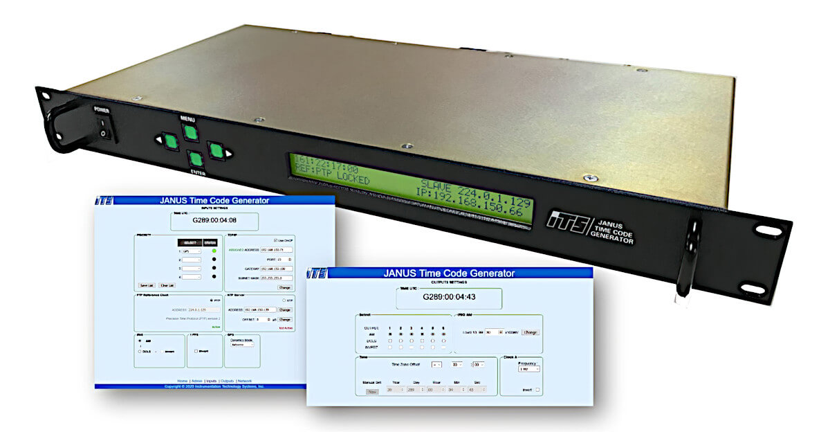
Time Code Generators
The 6115G-3E Janus Time Code Generator (JTCG), when synchronized to the internal GPS or and external 1PPS, may be set to perform as a local PTP Master Clock in accordance with IEEE standard 1588 V2 default profile.
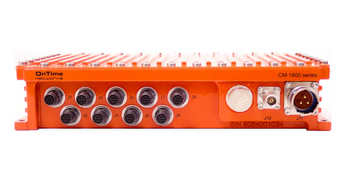
Switches
We offer a range of On-Time network switches that will act as a Grand Master Clock. Some will support the co-existence of Slave Devices operating either PTP V1 or PTP V2 on the same network.
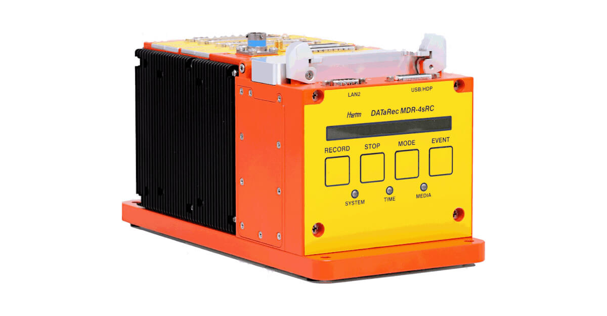
Flight Test Data Recorder
The MDR family from Safran Data Systems continues to set the standard in flight test data recording for today and tomorrow. With its internal GPS, the MDR is able to act as either a Grand Master Clock, Master Clock, or Slave Device.
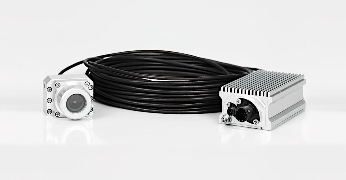
Flight Test Video Camera
The Full HD Flight Eye Camera FE 320 has been developed in close cooperation with OEM aviation clients, for very low latency performance on Ethernet networks in extreme airborne requirements. Can be time synchronised by a PTP V2 Master Clock device.
Disclaimer: The information in this guide is designed to help you understand our products. It is correct to the best of our knowledge and at the time of writing. However Photo-Sonics International Limited does not accept any liability for its use. Instead the latest documentation from the relevant authority should be consulted.