IRIG 200 Time Code Formats
Introduction:
Modern electronic communication systems, data acquisition, missile, aircraft, and spacecraft tracking systems require accurate time-of-day (TOD) and time-of-year (TOY) for correlation and compatibility within a test range, across test ranges, and beyond.
As of August 2016, IRIG 200-16 provided latest standard for serial time codes used in these and other applications. The previous update had been in September 2004 (IRIG 200-04).
N.B. Precision network Time Protocol (PTP) is become more commonly used to synchronize data across instrumentation system, you can read more about it in this article.
Formats, Frames, and Bits:
At their core, IRIG serial time codes consist of a continuous train of pulses (or bits) in which a collection of bits, called a frame, can be decoded to give a precision time and optionally provide some Control Functions (CF).
The number of bits per frame, and the speed at which the frames are repeated, i.e. the Frame Rate, is the key difference between each of the six serial time codes defined by IRIG 200-16.
These six time code formats have an alphabetical designation, A, B, D, E, G, and H (the latter replacing IRIG C). The table below provides a summary including available Control Function Bits.
| IRIG Time Code Formats, Bits and Frame Rates | |||||
| Format | Bits per Frame |
Frame Rate | Bit Rate | Control Function Bits |
|
| A | 100 | 10 Hz | 10 fps | 1,000 pps | 18 |
| B | 100 | 1 Hz | 1 fps | 100 pps | 18 |
| D | 60 | 1/3600 Hz | 1 fph | 1 ppm | 9 |
| E | 100 | 0.1 Hz | 6 fpm | 10 pps | 18 |
| G | 100 | 100 Hz | 100 fps | 10,000 pps | 27 |
| H | 60 | 1/60 Hz | 1 fpm | 1 pps | 9 |
Where
-
fps is frames per second
-
fph is frames per hour
-
fpm is fames per minute
-
pps is pulses per second
-
ppm is pulses per minutes
Without exploring the detail of a frame’s formatting, it’s worth pointing out that it is the leading edge of the second bit in a frame that provides the on-time reference point for the receiving instrumentation and that, for example, an IRIG B time code will provide an on-time reference point once per second.
Modulation, Frequency, and Code Expressions:
A three digit number follows the alphabetical format designation. This number indicates the time code’s characteristics in terms of Modulation Type, Frequency / Resolution, and Code Expression. These are listed in the table below.
| IRIG Time Code Syntax | ||
| Digit | Code | Definition |
| 1st Digit: Modulation Type |
0 | Pulse width code |
| 1 | Sine wave, amplitude modulated | |
| 2 | Modified Manchester modulation | |
| 2nd Digit: Frequency / Resolution |
0 | No carrier / index count interval |
| 1 | 0.1 kHz / 10 milliseconds | |
| 2 | 1 kHz / 1 millisecond | |
| 3 | 10 kHz / 10 microseconds | |
| 4 | 100 kHz / 1 microsecond | |
| 5 | 1000 kHz / 0.1 microsecond | |
| 3rd Digit: Code Expression |
0 | BCDTOY, CF, SBS |
| 1 | BCDTOY, CF | |
| 2 | BCDTOY | |
| 3 | BCDTOY, SBS | |
| 4 | BCDTOY, BCDYEAR, CF, SBS | |
| 5 | BCDTOY, BCDYEAR, CF | |
| 6 | BCDTOY, BCDYEAR | |
| 7 | BCDTOY, BCDYEAR, SBS | |
Where
-
BCDTOY is Time of Year; Seconds / Minutes / Hours / Days / Tenths of Seconds
-
BCDYEAR is the Year.
-
CF indicates an ability to contain Control Function.
-
SBS is Time of Day in Straight Binary Seconds, a 17 bit binary counter from 0 to 86399 (N.B. There are 86,400 seconds in a day).
So an IRIG B122 time code will be an amplitude modulated sign wave of 1 kHz providing 1 millisecond accuracy of the Time of Year. No information on the year is included, nor are there any Control Functions.
N.B. Earlier versions of IRIG A, B, E, and G did not provide for encryption of the year.
Binary Coded Decimal (BCD):
In Binary Coded Decimal each decimal digit is represented by a combination of four binary bits. Whilst in standard binary representation four binary bits provide a range of 0 to 15, in BCD the highest valid number that can be represented by four bits is 9.
The table below shows how the decimal number 56 can be represented in BCD as 0101 0110.
| BCD Representation | ||||||||
| Decimal Units | Tens | Units | ||||||
| Decimal Digits | 5 | 6 | ||||||
| BCD Digits | 0 | 1 | 0 | 1 | 0 | 1 | 1 | 0 |
| BCD Units | 80 | 40 | 20 | 10 | 8 | 4 | 2 | 1 |
N.B. When transmitted via IRIG the BCD representing units will be sent first, followed by the bits representing the tens. To represent minutes and seconds, only seven bits are required, four for units, and three for tens.
Permissible Code Formats:
As previously ascertained, an IRIG A time code will contain 1000 pulses per second. It therefore stands to reason that if IRIG A is to be modulated on a sinusoidal carrier, the frequency of that carrier must be greater than 1000 Hz.
With this and other factors in mind it is understandable that not all combinations of format, modulation, carrier frequency, and code expression are permissible. We can expand the IRIG Time Code Syntax table above to provide a quick look up reference.
| Permissible Code Formats | ||||||||
| Digit | Code | Definition | IRIG A |
IRIG B |
IRIG D |
IRIG E |
IRIG G |
IRIG H |
| 1st Digit: Mod. Type |
0 | Pulse width code | ✓ | ✓ | ✓ | ✓ | ✓ | ✓ |
| 1 | Sine wave, AM | ✓ | ✓ | ✓ | ✓ | ✓ | ✓ | |
| 2 | Modified MM | ✓ | ✓ | ✓ | ||||
| 2nd Digit: Freq. / Res. |
0 | No carrier / index count interval | ✓ | ✓ | ✓ | ✓ | ✓ | ✓ |
| 1 | 0.1 kHz / 10 ms | ✓ | ✓ | ✓ | ✓ | |||
| 2 | 1 kHz / 1 ms | ✓ | ✓ | ✓ | ✓ | |||
| 3 | 10 kHz / 10 μs | ✓ | ✓ | |||||
| 4 | 100 kHz / 1 μs | ✓ | ✓ | ✓ | ||||
| 5 | 1000 kHz / 0.1 μs | ✓ | ✓ | ✓ | ||||
| 3rd Digit: Code Exp. |
0 | BCDTOY, CF, SBS | ✓ | ✓ | ||||
| 1 | BCDTOY, CF | ✓ | ✓ | ✓ | ✓ | ✓ | ✓ | |
| 2 | BCDTOY, | ✓ | ✓ | ✓ | ✓ | ✓ | ✓ | |
| 3 | BCDTOY, SBS | ✓ | ✓ | |||||
| 4 | BCDTOY, BCDYEAR, CF, SBS | ✓ | ✓ | |||||
| 5 | BCDTOY, BCDYEAR, CF | ✓ | ✓ | ✓ | ✓ | |||
| 6 | BCDTOY, BCDYEAR | ✓ | ✓ | ✓ | ✓ | |||
| 7 | BCDTOY, BCDYEAR, SBS | ✓ | ✓ | |||||
where AM is Amplitude Modulation, and MM is Manchester Modulation.
Not all pulses are created equal:
Thus far we have covered everything most users of an IRIG serial time code would want to know, but for those who want a more detailed understanding, read on.
We have established that IRIG A consists of time and control functions wrapped in a frame of a hundred pulses, and that each frame is transmitted ten times per second. We know that binary coded decimal is use to encode the time, and we have taken a look at how binary coded decimal works.
Let us inspect the pulses themselves. Perhaps unexpectedly, the duration of the pulses will vary, and it is the duration of the pulse within it’s 1 millisecond window that signifies the bits meaning.
The longest pulses, 0.8 milliseconds in the case of IRIG A, are reserved for the position identifiers and the reference bit. The first and every tenth bit is a position identifier and are referred to as P0, P1, P2, P3, P4, P5, P6, P7, P8, and P9.
As previously mentioned, the reference bit (Pr) is the second bit in the frame and provides the decoding equipment with the on-time reference point at its leading edge.
A pulse of a 0.5 millisecond duration represents a binary 1, whilst a 0.2 millisecond pulse represents a binary 0.
N.B. These pulse durations apply for IRIG A formats and by necessity are different for the other five serial time codes.
The BCDTOY (Time of Year) is represented by 34 bits. 7 bits are used to encode seconds, 7 bits for minutes, 6 bits for hours, 10 bits for days, and 4 bits for tenths of seconds.
The IRIG 200-16 standard illustrates the first 50 milliseconds of a 100 millisecond IRIG A frame, that portion containing BCDTOY, as below.

The above stream can be read as 42 second, 18 minutes, 21 hours, 173 days, and 0.875 seconds.
The second half of the 100 millisecond frame begins with the BCDYEAR information is encoded in eight bits and is a number in the range of 0 to 99.
18 bits of Control Function then follow between position identifiers P6 and P8. After P8 is the Time of Day in Straight Binary Seconds (SBS), a 17 bit binary counter from 0 to 86399 (N.B. There are 86,400 seconds in a day).
The IRIG 200-16 standard illustrates the second 50 milliseconds of a 100 millisecond IRIG A frame like this.

IRIG B, D, E, G & H Serial Time Codes follow similar structures. For further details please consult the Range Commanders Council (RCC) latest published IRIG 200 standard.
Photo-Sonics International Ltd offer a comprehensive range of rackmount, handheld, and cockpit IRIG Time Code Generators. Video Inserters are also available to add IRIG overlays onto multiple video streams.
IRIG Time code generators and video inserters
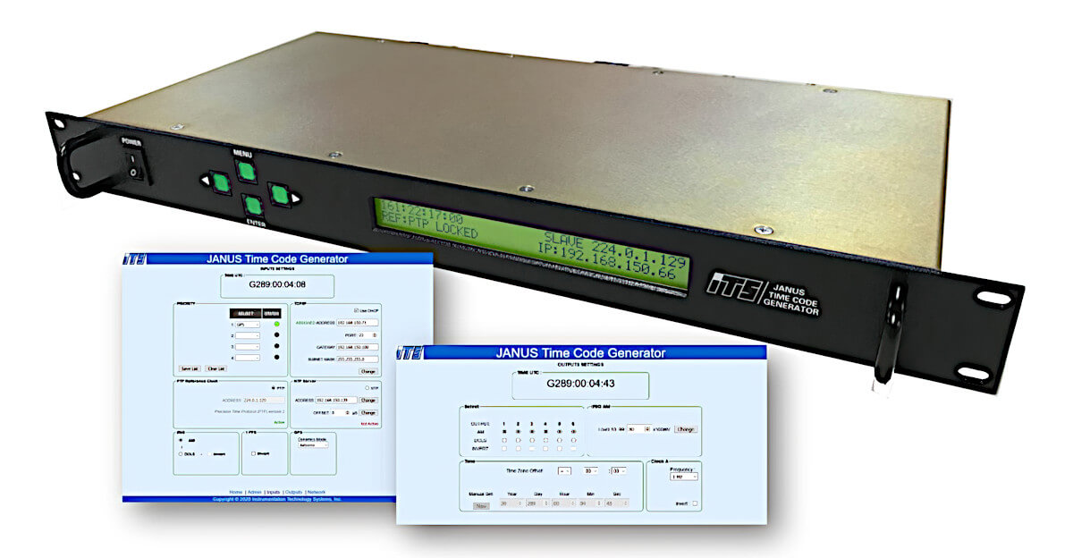
IRIG Time Code Generators
A comprehensive range of rackmount, handheld, and cockpit IRIG Time Code Generators.
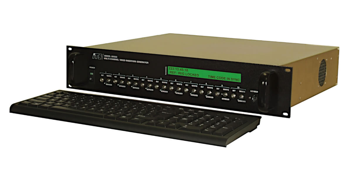
IRIG Video Inserters
A comprehensive range of rackmount and vehicle mount IRIG Video Inserters.
Disclaimer: The information in this guide is designed to help you understand our products. It is correct to the best of our knowledge and at the time of writing. However Photo-Sonics International Limited does not accept any liability for its use. Instead the latest documentation from the relevant authority should be consulted.